| Bare Bones
Board (BBB) Visual Build Instructionsr /> By Dataman Aka Charley Jones, PMP Panels8x8@CRJones.Com For ModernDevices.Com |
 |
|
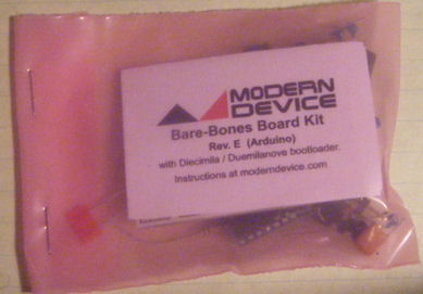
KIT CONTENTS |
|
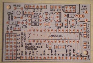
| Printed Circuit Board The side of the boarding with the writing on it is called the silk screen. This is the side to which we'll mount a majority of the components. |
 |
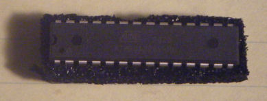
| 1 CPU This little chip contains 32k ROM, 2k RAM, and 18 I/O pins. This entire circuit is built to support this one chip. |
 |
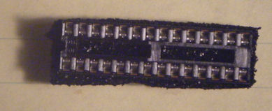
| 1 Chip Socket One chip socket is provided to support the cpu. |
 |
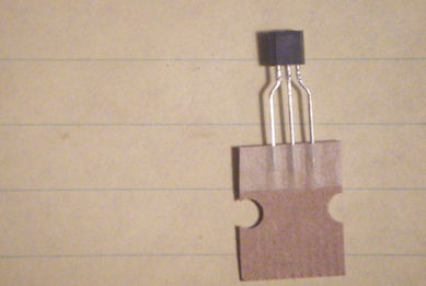
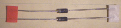
| 1 5v/250ma Power Rectifier This highly efficient power recifier provides 5v of power at 250ma. Great for low power applications. |
 |
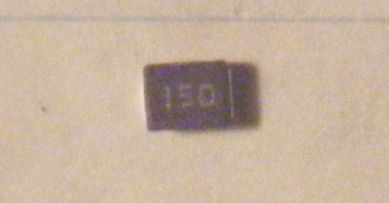
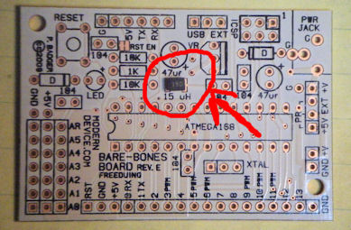
| 150uh Surface Mount Inductor The tiniest piece of the build is the optional 150uh surface mount inductor. While daunting at first, this is a great opportunity to see how easy surface mount can really be. |
 |
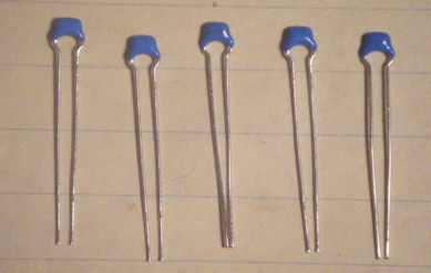
| 5 1.uf Ceramic Capacitors These 5 ceramic capacitors may be inserted into the board in either direction. |
 |
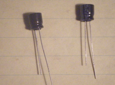
| 2 Electrolytic Capacitors These larger capacitors are polarized and the long leg must be placed in the hole marked + for the circuit to work properly. |
 |
| 2 Diodes 2 diodes are used to protect the circuit from reversed voltage. These devices are polarized and the white line must be lined up with the band mark on silk screen. |
 |
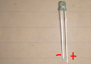
| 1 LED This LED will indicate that power is flowing to the board. This device is polarized with the longer leg being +. This part may be omitted in low power configurations. |
 |
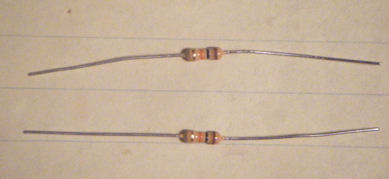
| 2 10K Ohm Resistors 2 10k ohm resistors are provided. The resistors are marked Brown Black Orange. Be careful, Orange and Red can be difficult to tell apart. Use a magnifying glass or check with your ohms meter. |
 |
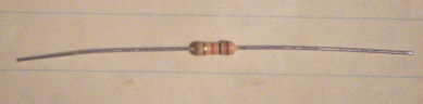
| 1 1k Ohm Resistors The resistor is marked brown black red and is the current limiting resistor for the LED. |
 |
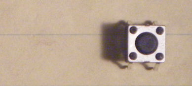
| 1 Button This button will act as the reset button for the circuit. Pressing this button will recycle the processor. |
 |
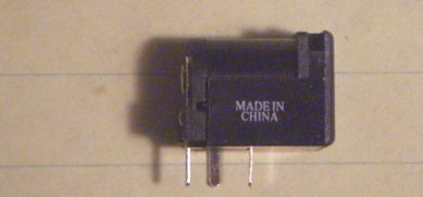
| 1 Power Connector This 2.1mm / Type M male jack is used to provide 6-9v DC power to the BBB. |
 |
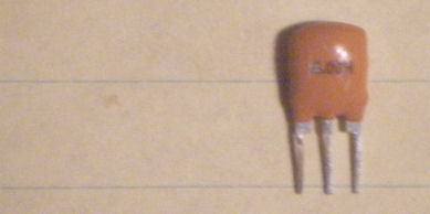
| 1 Resonator This 16mz resonator module is central to the clock circuit of the BBB. It's non-polarized, but is typically placed so the face can be read. |
 |
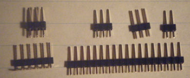
| Various Male Header Male header is provided in a variety of types and sizes: 1x 2-Pin Single Row Male 2x 3-Pin Single Row Male 1x 3-Pin Double Row Male 1x 6-Pin Right Angle Male 1x 18-Pin Single Row Male |
 |
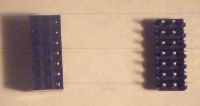
| 21-Pin Connectors The 21-Pin connector is provided in both male and female version. It's your chioce which to solder, or not at all. |
 |
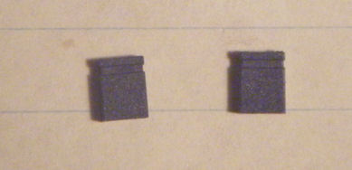
| 2 Shunts These two shunts are used to set the board configuration. |
 |
|
OPTIONAL ADDITIONAL COMPONENTS |
|
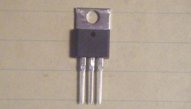
| High Power Rectifier While the super efficient 250ma power regulator is great, the 7805CT is it's high powered big brother delivering 5v at 1.5amps. The Panel8x8 assembly requires lots of power, so opting for a bigger rectifier greatly increases the usefulness of the BBB. |
 |
|
MAIN BUILD |
|
| Install the Inductor Soldering this component is as simple as gluing it in place (with temporary tack) and glopping some solder on the ends. This part can be omitted by bridging the gap with solder, but you're missing out on a great opportunity to practice surface mount! |
 |
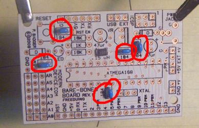
| Insert Ceramic Capacitors Insert and solder the 5 ceramic .1uf capacitors as shown. The devices are non-polarized and may be inserted in either direction. |
 |
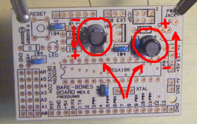
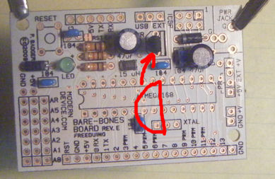
| Insert Electrolytic Capacitors Insert the 2 eloctrolytic capacitors as shown in the photo. Note that the left, the + faces down, where on the right, the + faces up. |
 |
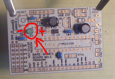
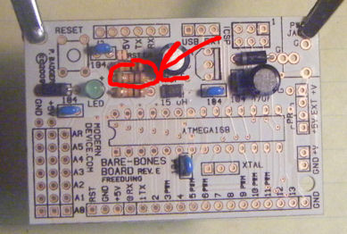
| Insert LED Optionally insert the LED if you would like indication that power is supplied to the board. Note the orientation in the photo. |
 |
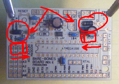
| Insert Diodes Next insert the diodes. Note that the Left diode faces right and the right diode faces left, as shown in the photo. |
 |
| Insert 10k Resistors Insert and solder the 2 10k resistors. Be certain that you have chosen the Brown Black Orange resistors. |
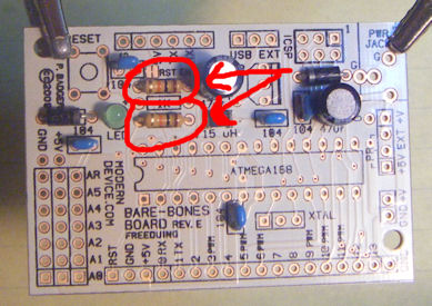 |
| Insert 1k Resistor Insert and solder the 1k resistor, brown black red, as the current limiting resistor for the LED. |
 |
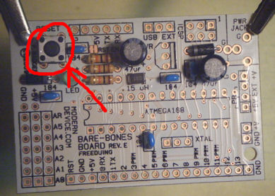
| Insert Button Insert and solder the reset button. |
 |
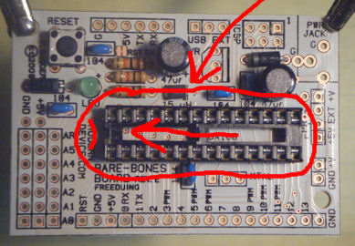
| Insert Chip Socket Insert and solder the chip socket observing that the notch should face left as in the picture. You may place a piece of foam under the socket to solder, or simply bend the first and last pin to hold it in place while soldering. |
 |
| Prepare Chip Roll the Chip on the perpendicular to the desktop on both sides to align the pins. |
 |
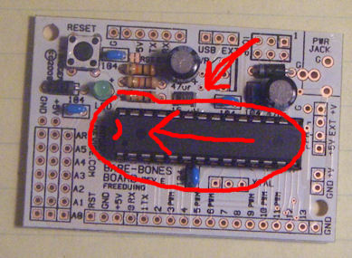
| Insert CPU Carefully insert the CPU into the socket being certain not to crush any of the pins. Observe that the notch in the chip must face left as in the photo. It may take some force to get the chip into the socket. |
 |
| Insert Low Power Rectifier If choosing the high power rectifier, skip to the next step. Depending on which configuration you've chosen, high or low power, insert the low power rectifier as shown. The curved part should face to the left, while the flat part faces to the right. |
 |
| Insert High Power Rectifier If inserting the high power rectifier, note that it is insert opposite of the low power rectifier. The shiny power-sink faces left, while the sqaure black front faces to the right. |
 |
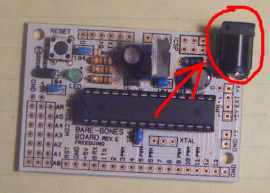
| Insert Power Jack Insert and solder the power jack if desired. This will allow you to easily supply DC voltage to the circuit using a standard 2.1mm/Type M power supply. |
 |
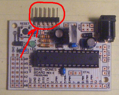
| Attach Programming Header Solder in the right angle header to provide a connection for a USB BUB or programming cable. |
 |
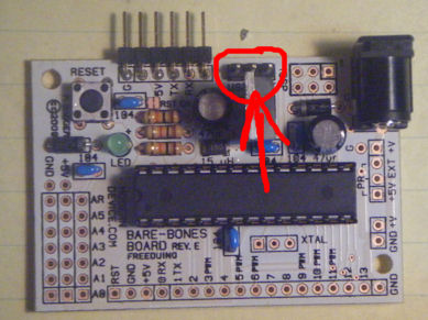
| Attach Power Source Selector Use one piece of 3-Pin male to provide configuration options for power source. |
 |
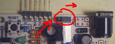
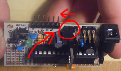
| Set Source to External As in this photo, place the first shunt over the EXT pins to select External power for later testing. Better to blow up a power supply than your laptop! |
 |
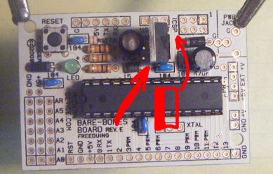
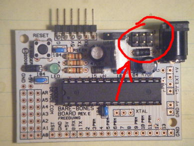
| Attach ICSP Header Use the 2x3-Pin male header to create an ICSP connector for the BBB. This allows programmers and other devices to connect to the board. |
 |
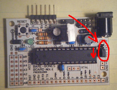
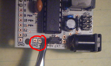
| Select Rail Pin Source Solder in the remaining 3-Pin male header to create the Rail Pin Source Selector. Note that the 3-Pin header goes in the bottom 3 holes of this 4 hole connection. Place a shunt over 5v to supply regulated 5v power to the rail pins. |
 |
|
OPTIONAL INSTALLATION |
|
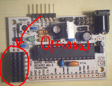
| Optional Analog Connector If desired, solder in the optional analog connector in either female or male version. The female version provides a breadboard like interface for inserting components. |
 |
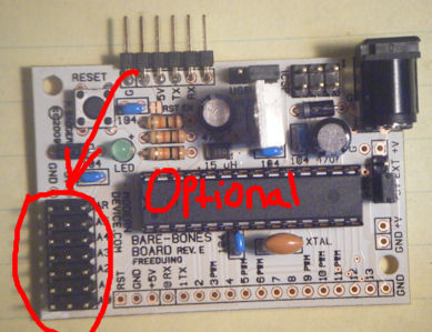
| Optional Analog Connector The optional male header allows easy connection to standard .1" spaced cables or connectors. |
 |
| Solder Connection Header If configuring for Panel8x8 skip this step. Optionally you may solder all remaining pins of the BBB to the 18-Pin male header. Plugging the BBB into a breadboard provides full access through these pins. |
 |
|
MAIN ASSEMBLY CONTINUED |
|
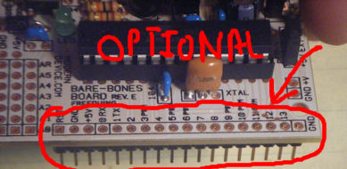
| Panel8x8 Header If configuring this BBB for the Panel8x8 assembly, only solder pins 4,5,6 and 7 to male header. Note that Pin 1 RST of a full assembly would conflict with the power interconnect and would need to be trimmed off. |
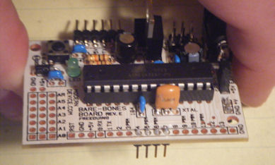 |
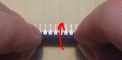
| Solder Rail Pins
If desired, solder the rail pins with the remaining 2 pin connector to the bottom of the board as indicated. In the basic Panel8x8 configuration, these pins provide power to the array. |
 |
|
TESTING |
|
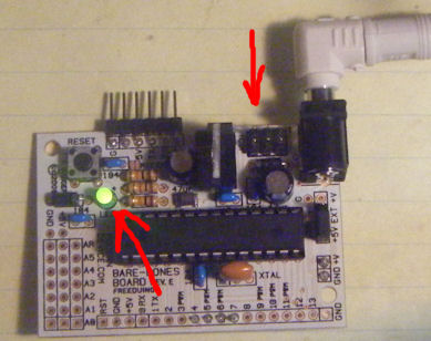
| Test External Power Connect a 6-9v power supply to the BBB to test the circuit. If the green light comes on, the circuit has been properly assembled. |
 |
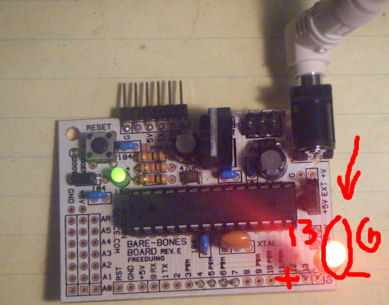
| The Blink Test In addition to the standard bootloader, Paul has been initally programming his CPUs with the blink program. Place an additional test LED betwen pins 13 and Ground, 13 being +. You should see the LED blinking. If not, it's possible the blink sketch was not loaded. |
 |
| Select USB Power Source Disconnect power and move the Power Selector shut to USB. This will allow the BBB to power from the USB cable. |
 |
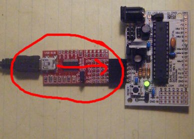
| Attach USB BUB Connect the USB BUB and mini cable to the BBB for testing. You could now try uploading the Blink Program if that test failed earlier. |
 |
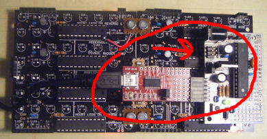
| Connect to Panel8x8 Array If connecting to the Panel8x8 array, simply plug in the BBB to the rightmost panel. Some sticky tape should be used to protect the BUB from shorting against the interconnect. |
 |
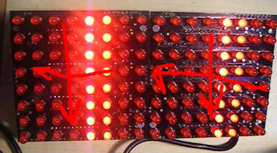
| Upload Test Program Panel8x8 Library Example 4 is a handy program to test Panel & BBB operation. LEDs should sequence top to bottom, then right to left. Every LED should be at one time during a full cycle. A BUB is sufficient to power 4 panels in this configuation. Happy Hacking! -Dataman |
 |