| USB BUB Visual Build Instructions By Dataman Aka Charley Jones, PMP Panels8x8@CRJones.Com For ModernDevices.Com |
 |
|
KIT CONTENTS |
|
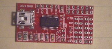
| Printed Circuit Board Most of the assembly of the USB BUB has already been done. We'll only need to add a few support and interface components. |
 |
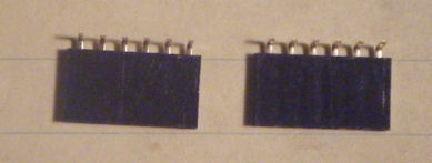
| 2 Female Headers Only 1 of the 2 female headers included is required for this build. The other is optional for creating a custom connection. |
 |
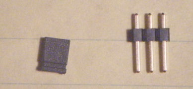
| 1 Male 3 Pin Connector and Shunt These pieces are used to create 3.3v/5v selection switch. |
 |
|
REQUIRED COMPONENTS |
|
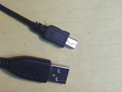
| USB A to USB Mini cable The required cable for this device is a straight USB A to USB Mini cable, the type found shipped with many cameras. This is just normal USB Mini cable. The kit may be ordered with or without this cable, and for most applications, the cable will be required. |
 |
|
MAIN BUILD |
|
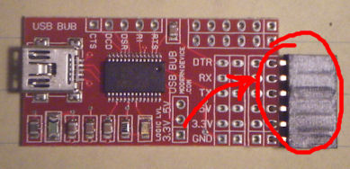
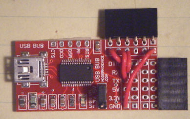
| Add Female Header Add the female header to right/bottom of the board. This connection has been prewired to connect to a Bare Bones Board (BBB). |
 |
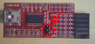
| Add the 3.3/5v Selector While the board has been prewired for 5V, which is what we need for the BBB, providing the option of selecting 3.3v for something like the Arduino Pro, greatly increases the flexibility of this board. |
 |
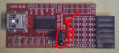
| Add the Shunt to 5v Place the shunt on the top 2 pins of the selector. This sets the board to 5v mode. |
 |
|
OPTIONAL BUILD |
|
| Optional Breakout Connector The optional connector may be used to support other devices not using the standard pinout. By jumpering lines, you may provide additional support to an additional device. In this case, Receive and Transmit have been swapped, and 3.3v/5v support has been dropped. Use of the breakout connector is not required is most circumstances. |
 |
|
FINAL ASSEMBLY |
|
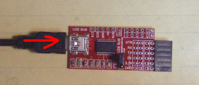
| Plug in the USB Mini cable Lastly, plug in the USB Mini cable. You're now ready to use the USB Bub. Happy Hacking! -Dataman |
 |