| LCD Support Visual Build Instructions By Dataman Aka Charley Jones, PMP Panels8x8@CRJones.Com For ModernDevices.Com |
 |
|
KIT CONTENTS |
|
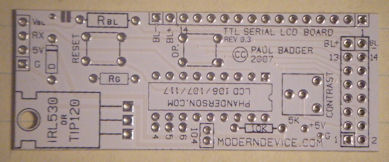
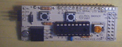
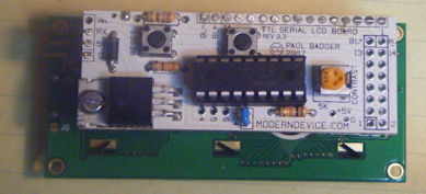
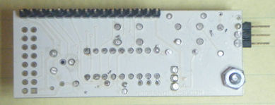
| Printed Circuit Board The side of the boarding with the writing on it is called the silk screen. This is the side to which we'll mount a majority of the components. |
 |
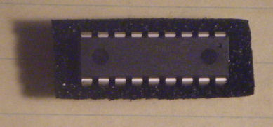
| 1 CPU This little chip provides all the logic necessary to provide serial communications to the host controller and drive the LCD display. |
 |
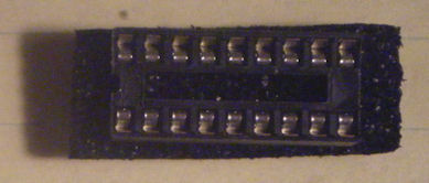
| 1 Chip Socket One chip socket is provided to support the cpu. |
 |
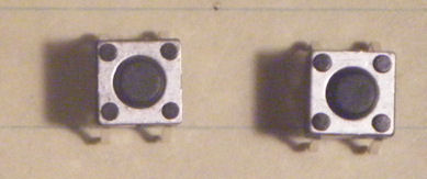
| 2 Push Buttons Two push buttons are provided to support sending commands to the cpu. |
 |
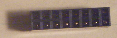
| 2 Female Headers Only 1 of the 2 female headers included is required for this build. The other is optional for creating a custom connection. |
 |
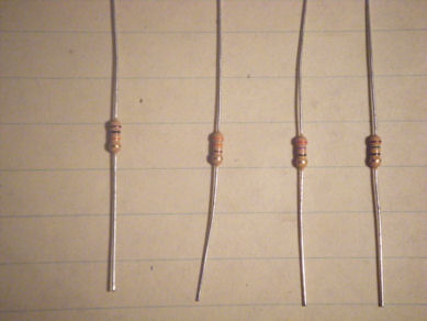
| 4 Resitors Resistors are provided in 4 different sizes. 10k = Brown Black Orange 330 = Orange Orange Brown 27 = Red Violet Brown 17 = Brown Green Brown Not all resistors will be used by this circuit and some research may be required to select the proper resistor combination. |
 |
| 2 Buttons 2 buttons are used on the LCD board to send various commands to the cpu. |
 |
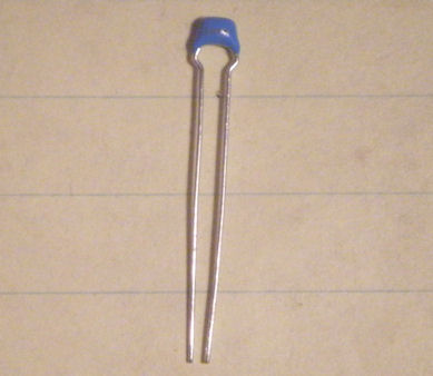
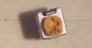
| 1 5k Potentiometer The 5k potentiometer is use as the contract control on the LCD board. |
 |
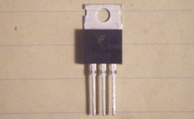
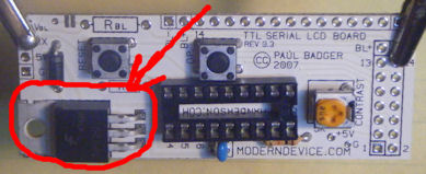
| 1 TIP 120 Transistor The large switching transistor is used on the LCD board. |
 |
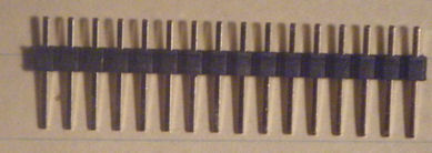
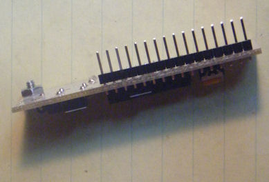
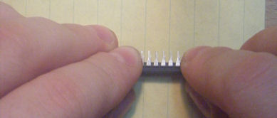
| 1 16-Pin Single Row Male Header 1 male header is included in the kit and used to connect the LCD board to the display. |
 |
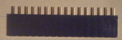
| 1 16-Pin Single Row Female Header One set of female single row header is included. This header is to be soldered to the LCD Display to allow connection to the LCD board. |
 |
| 2 Double Row Remale Header This optional connector may be used to provide access to the signals, or to connect to different types of LCDs. |
 |
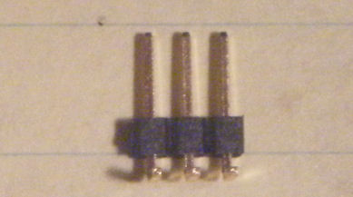
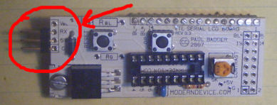
| 1 3-Pin Male Header Either the straight or 90 degree male header may be used to provide a point to connect a servo cable for communications. |
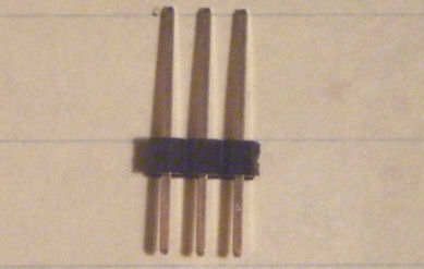 |
| 1 3-Pin Male 90-Degree Header Either the straight or 90 degree male header may be used to provide a point to connect a servo cable for communications. |
 |
|
REQUIRED ADDITIONAL COMPONENTS |
|
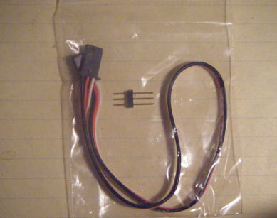
| 3 Wire Servo Cable & Connector The kit may be ordered with an optional 3 wire servo cable and connector. This makes it easier to the hook up the board to any microcontroller, especially an arduino clone mounted and a breadboard. |
 |
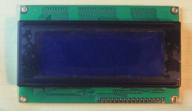
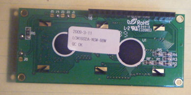
| LCD Display To use the LCD panel you will need some sort of LCD display. Low cost/compatible displays are carried at ModernDevice.Com |
 |
|
OPTIONAL COMPONENTS |
|
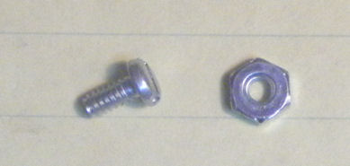
| #4 Screw and Bolt To better secure the trasistor, you may optionally use a #4 screw and bolt, which is quite common in kit building. |
 |
|
MAIN BUILD |
|
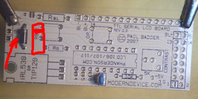
| Insert Capacitor Insert and solder the only capacitor in this project. The capacitor is non polarized and may be inserted in either direction. |
 |
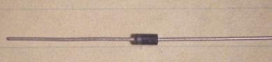
| Insert Diode The diode potects the circuit from reverse voltage and must be inserted correctly for the circuit to function. The white band should face the top of the board as demonstrated in the photo. |
 |
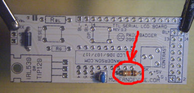
| Insert 10k Resistor The 10k resistor is inserted next. It too is non polarized. The color markings should be Brown Black Orange. You can verify with an ohms meter if unsure. |
 |
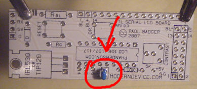
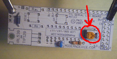
| Insert Potentiometer The potentiomer is inserted next. Using a mini screwdriver, turn the potentiometer all the way to the right. |
 |
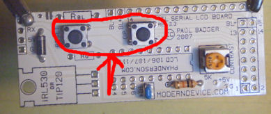
| Insert Buttons Now is a good time to insert and solder the buttons. Due to the circuit design, these may be inserted in either direction. |
 |
| Insert Chip Socket Now is a good time to solder the chip socket. The notch should face to the right. You may use the piece of packing foam to support the chip while you solder, or simply bend pins in opposite corners to hold the chip in place. |
 |
| Insert Transistor Next the transistor is bent into shape and inserted. The transistor may also be attatched using the #4 screw and bolt. |
 |
| Insert Male Header Depending the configuration of your LCD board, attach and solder the 16-Pin Male Connector to the bottom of the board. |
 |
| Attach Power/Data Connector Your choice of the 3-Pin connector here. The right angle connector seems to provide a simpler connection the board. |
 |
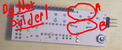
| Insert Rbl and Rg Insert the 330 ohm resistor (Orange Orange Brown) in Rg. Insert the 27 ohm resistor (Orange Violet Brown) into Rbl. DO NOT SOLDER these resistors yet. |
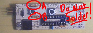 |
| Trim Resistor Trim the resistors short and bend back careful to avoid contact with anything else. Test the board before soldering these resistors in place. |
 |
| Prepare Chip Roll the Chip on the perpendicular to the desktop on both sides to align the pins. |
 |
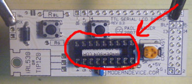
| Insert Chip Insert the cpu chip into the socket observing that the notch should face to the right. |
 |
| Attach Female Header Attach the 16-Pin female header to the LCD. |
 |
|
FINAL ASSEMBLY |
|
| Attach LCD Board to Panel Plug the LCD Board into the LCD Panel. |
 |
| Attach Data Cable Attach the data/power cable. The black cable should be on the bottom. |
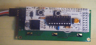 |
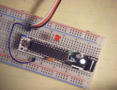
| Cable to Micro Controller In this photo, the LCD Panel is cabled to a RBBB micro controller. Conveniently Ground and 5V line up at one side of the board. All that's left is to hook up the transmit line (Digital Pin 1) to the white wire. |
 |
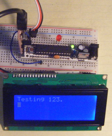
| Simple Program Test Connect the Micro Controller to your computer, start Arduino Studio and run this simple program: void setup() { Serial.begin(9600); //9600 Baud Serial.print("?Bff"); //Turn on Backlight delay(100); //Wait 100ms Serial.print("?f?a"); //Clear & Home Serial.print("Testing 123.?n"); //Txt + LF } void loop() { } NOTE: It's best to unplug the LCD panel when uploading programs. Programming responses sent over Tx may confuse the LCD Board and require unplugging it anyhow. Just reconnect and reset the micro controller to start your program. |
 |
| Program Notes Our first command ?Bff was to turn on the backlight. A 100ms delay is required after the set backlight command. The LCB Board automatically remembers settings for things like backlighting so we won't need to the send this command again. |
?f?a Clears the screen and homes the cursor. ?n is a linefeed command, which forces the display to progress to the next row. More commands can be found at: http://moderndevice.com/ LCD117CommandSummary.htm |
Finally Now that you know everything is working, solder the two resistors. If you did not use Lead Free-No Clean solder, brush the entire board down with alcohol to remove chemical residue. Failure to do so so will result in later board failure. You're now ready to use the LCD Board. Happy Hacking! -Dataman |
 |