Multichron V1.1 GPS Modification
Along with the Version 1.1 MultiChron softare, CaitStith and Dataman
provided a GPS Modification to the MonoChron clock. This
modifcation requires no further modification to the Monochron than 1)
Installing the firmware, and 2) Plugging the GPS module into the
MonoChron.
Click here to jump to instructions on operating up the GPS module.
Setup:
While the GPS Module module requires no physical changes to the
MonoChron, it does require a bit of work to set up. For my
modification I used Lady Ada's GPS Shield and module as that's what I
had handy. This modification does not make any permanent change
to clock or module. The GPS module can be removed and repurposed
elsewhere. Just don't slam the clock in the morning.
Requires:
Adafruit GPS Shield
Adafruit Stacking Headers
3 - 8 Pin 1." Female
2 - 6 Pin .1" Female
GPS Module
Some wire
Rubber band
Comple the build of the GPs module. I used stacking headers to
have female jacks on the top of the shield. I added another row
of standard female headers, and female header for the GPS block to
simplify repurposing.
Jumper GPS module as follows:
pin 3 to arduino +5,
pin 4 to Ground.
It wont work without these jumpers.
Now you will make up 2 sets of cables, about 6-9" each,
The longer the easier to work with.
Strip 1/2" from one end of the each cable,
About about 1/8" from the other side.
We'll be soldering the 1/8" side to .1" male header.
You'll need a 3 piece and 1 piece male.
You'll also want to glob a little bitt of solder on each pin.
We need to make the wider, ideally, fatter at the back (cable) side,
Thinner at the front.
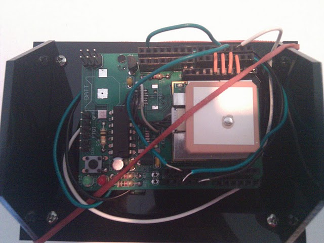
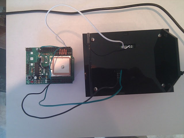
Ok, next we're going to secure the shiled to the clock with a rubber band,
Yes, a rubber band.
Hook one end on the bottom corner of the clock,
Other on the upper opposite side.
Run 1/2 around the edge of the clock.
Should appear as follows:
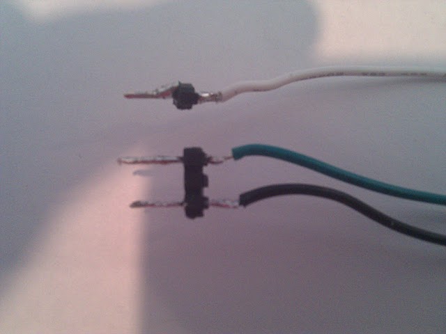
Next install the power and data cable.
In my power cable, black and ground, and green is power.
The rx data pin is the third from the right.
The pins should fit snuggly.
At this point you may want to test the cables and power.
Cable as follows;
5v (green) power cable.
GND (black) ground cable.
Pin 2, (White) data cable.
Power up the module.
The GPS light should turn on, recheck cables,
Especially firmness of the power plug.
You may also carefully flip over the clock,
And run through the configuation instrustions to make sure you have a good data stream.
Disconnect the power and cables from module when done.
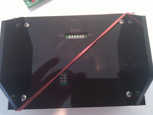
Carefully bend the cables to the outsides of clock,
And drop the GPS module under the rubber band.
The shield pins will force the module to stand off the board.
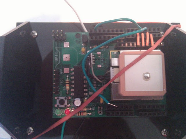
Wrap the power cables under and around the rubber band and module to tension the cable.
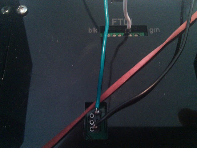
End with the cables plugged into 5v (green) and GND (black) on the shield.
The data cable (white) plugs into pin 3.
Carefully smush down the cables a bit.
The plug in the clock.
Look for the red led on the GPS module itself.
If no red light, something is wrong, go back and check.
Operation:
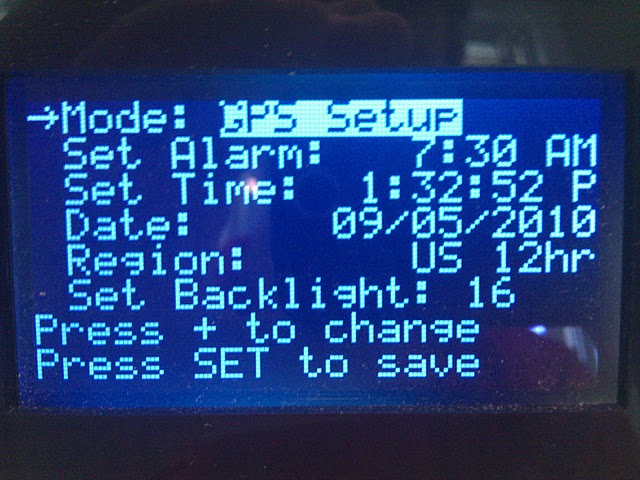
To configure the GPS module,
1) Hit menu button
2) Scroll Mode to to the GPS Setup Screen
3) Hit SET.
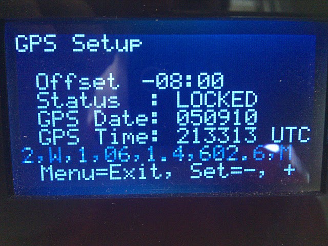
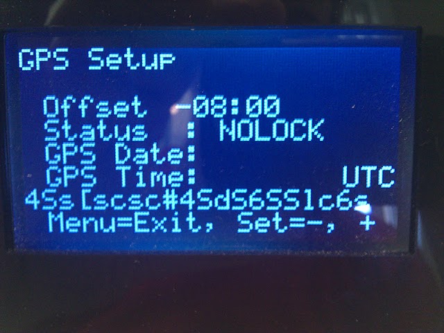
With the GPS Setup screen shown, the system immediately begins polling
the GPS in diagnostic mode. The second line from the bottom
displays incoming raw data from the GPS module. The data will
flash by too fast to read, but if the data looks readable, numbers,
commas, and alpha, then the GPS module is hooked up properly. If
the GPS has a clear signal and communicates data properly, the Status
changes from NOLOCK to LOCKED.
If you are receiving a good stream of data, but can't get a lock, move
your clock nearer to a window or outside wall. The GPS module
must receive a Longitutde coordinate to lock.
You might also be getting a bad stream of data from the GPS
module. The following picture demonstates a bad data
stream. This problem was corrected by tying the GPS's RX line to
+5v.
With good GPS data coming in, set the TimeZone offset by + Key for plus
and the Set Key for minus. Pressing Menu exits this screen and
saves the TimeZone data to EEPROM. Once TimeZone is set, it does
not need to be reset until you reload EEPROM again.
Credits & Disclaimer:
Even through Dataman wrote the majority of the GPS code, huge thanks go
to CaitSith for implementing a circular buffer, and finally getting it
working. All this work was done for the love the MonoChron
clock. Neither of us are employees of Adafruit.Com nor is
Adafruit.Com responsible for this code.